CB-Technology (Connor Benton)
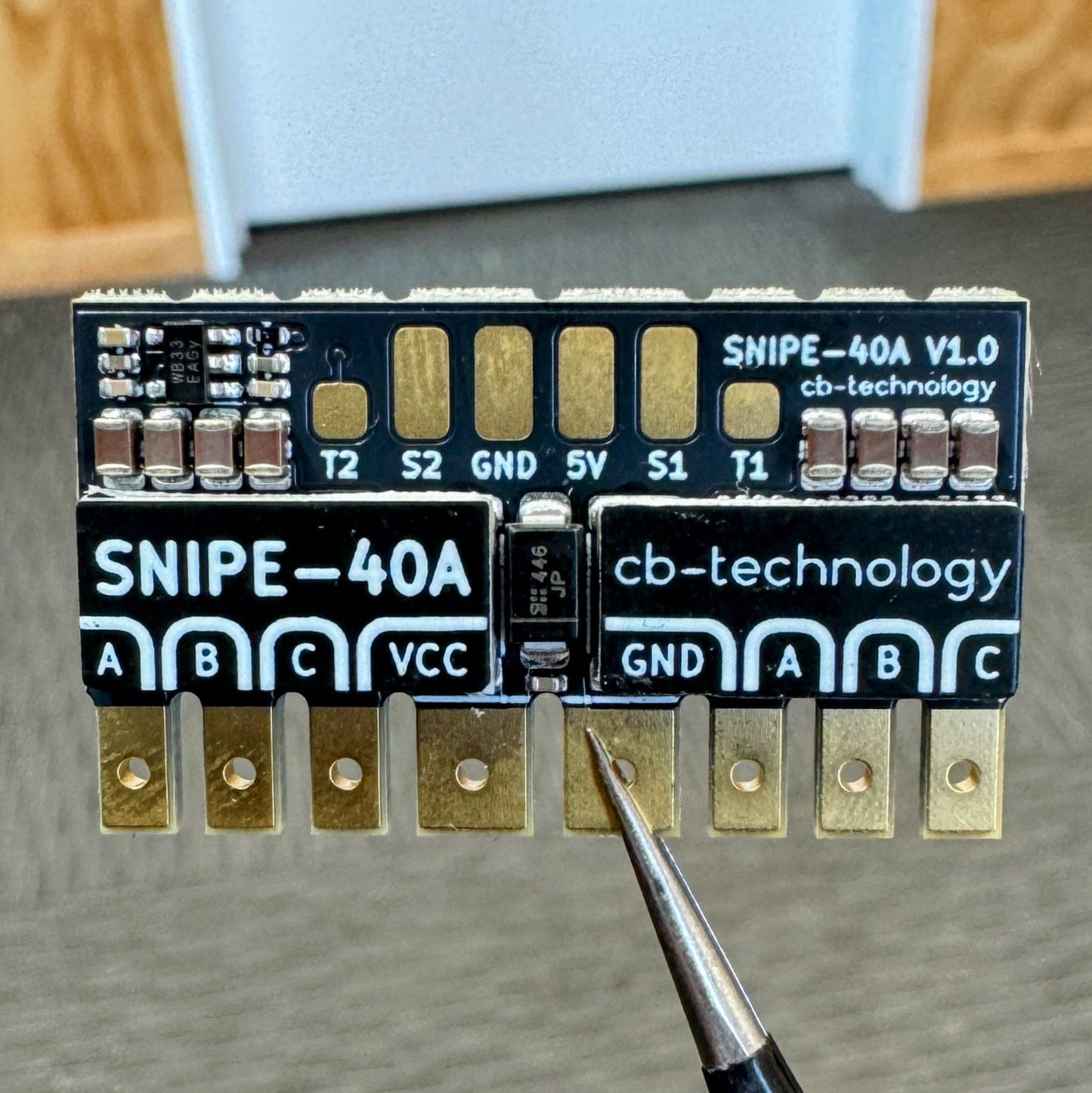
SNIPE Dual 40A AM32 ESC
SNIPE Dual 40A AM32 ESC
Couldn't load pickup availability
The SNIPE is a compact dual brushless motor speed controller (BLDC ESC), designed for high-performance drive systems in combat robotics and beyond. This is based on the architecture of the proven WEKA platform but now expanded to brushless motors, delivering smooth and responsive control with flexible input mapping and protocol options.
The product is named after the Campbell Island Snipe, a rare flightless bird once thought extinct but now know for its stealth, resilience and agility in the dense undergrowth of New Zealand's remote subantarctic islands.
Developed, assembled, and tested in Christchurch, New Zealand, by Connor Benton.
- Dual Bi-Directional BLDC-motor outputs.
- Dual blue status LED's to indicate run, fault and calibration modes.
- Separate red power LED to indicate the ESC is ON.
- User configurable under-voltage, over-current, over-temperature, and stall protections.
- Internal BEC to provide power to the radio reciever.
- Intelligent channel-wise failsafe behaviour.
- Simon-sais calibration process to customise drive modes, channel mapping, and channel inversion.
- TVS protection diode to reduce risk of transient voltage spikes during impact loading
- Only program the settings once for both motor outputs. No need to program both sides individially.
- Axilary Servo PWM ouptut to control external ESC's (Only available when using CRSF input).
- Dimensions: 35x20x6 mm
- Weight: 7g excluding wires
- Voltage Input: 2-6S LiPo (6.0-26.1V)
- Motor Output: 40A per channel
- BEC: 5V, 250mA. Designed to power the radio reciever but no servos.
- Signal Input: Servo PWM, CRSF
- Auxilary Signal Output: Servo PWM
- 1x SNIPE-40A Dual ESC
- 1x 35V 470uF capacitor
- 1x 35mm Heatshrink
- 1x 90mm XT30 14AWG power input cable
- 2x 90mm MR30 18AWG motor output cable
- 1x 90mm 3p DuPoint signal input cable
- 1x 90mm 1p DuPont signal input cable
- 1x XT30 Connector (opposite mating type to cable)
- 2x MR30 Connectors (opposite mating type to cable)
There are 3 LEDs on the SNIPE (1x red, 2x blue). The red LED is in the center and a blue LEDs are on each edge beside the motor outputs. See table below to detail LED behaviour:
| State |
Red LED |
Blue LEDs |
|
|---|---|---|---|
| No Power | OFF | OFF | |
| Idle | ON | OFF | |
| Driving | ON | ON | Each blue LED will immunimate when their corresponding input is being driven. |
| Fault Signal-Input |
ON | ALTERNATING FLASH | 1Hz |
| Fault Under-Voltage |
ON | FLASH | 1Hz |
| Fault Over-Temp |
ON | FAST FLASH | 5Hz |
| Calibration | ON | PATTERN | See Calibration section for specific LED patterns |
Each time the SNIPE powers on, it runs an auto-detect sequence to identify the connected radio protocol. It first tries the last known protocol, then cycles through all supported protocols until a valid signal is found. Once detected, the protocol is saved and the system immediately enters normal operation. If no valid signal is detected, the SNIPE enters a signal-input fault state.
Note 1: Some receivers take a few seconds to link with the transmitter when powered on. In this case the SNIPE will enter a signal-input fault state during this time. The fault state will clear automatically once the receiver connects and a valid signal is detected.
Note 2: If you change the radio protocol while the SNIPE is powered ON, it will NOT detect the new radio instead treating it like a Signal-Input fault. In this case you just need to power cycle the device and it will detect the new protocol.
The SNIPE has 2 input pads labelled S1 and S2. When using a standard Servo PWM input signal, both of these channels are required to control both motor outputs. Although, when using a single-wire serial protocol, like CRSF, only S1 is used. In this case, the SNIPE enables an additional function acting like a protocol decoder and repurposes the S2 connection as an auxilary output to control external ESCs. The process to enable/disable this function and which channel is mapped to this output are outlined in the Calibration section.
Note: If you enable this feature and then connect a radio with servo PWM, it will override this feature, temporarily disabling it until a CRSF radio is reconnected.
SNIPE continuously monitors for several fault conditions during operation. The monitored faults, listed from highest to lowest priority, are:
-
Over-Temperature: An over-temperature fault occurs when the sense circuit reaches the threshold temperature. The threshold is user-definable, steps are detailed in the configuration section.
-
Under-Voltage: An under-voltage fault occurs if the battery voltage falls below the threshold voltage. This threshold can be set per cell, absolute voltage, or disabled. This threshold is user-definable, and can be set on a per cell or absolute voltage: the steps are detailed in the configuration section.
Important note: When the SNIPE is powered ON, it automatically detects how many cells your battery has to set the appropriate low voltage level. Some battery cell counts have a voltage overlap with adjacent counts, see table below. So, the SNIPE then assumes the battery is more charged when powering on to solve the overlap. If you start up with a low battery, it might detect and set the undervoltage threshold too low. To avoid issues, we recommend powering on with a fully-charged battery.
Battery Cells Low Voltage High Voltage At Risk Percentage Overlap 2s 6.0V 8.70V No n/a 3s 9.0V 13.05V No n/a 4s 12.0V 17.40V Yes 19.4% -
Signal-Input: SNIPE uses an intelligent failsafe system that monitors each input channel individually. It only triggers a fault if a channel mapped to an output is lost. Here's how the failsafe works:
- Only mapped channels matter.
- Example: If Channels 1 and 3 are mapped to outputs, but Channel 4 is unused, losing Channel 4 won’t trigger a fault.
- Faults are channel specific:
- Example: In arcade drive mode, if the throttle channel is lost, the motors stop driving forward/backward, but turning and servos still work.
- The LED will show a signal-input fault whenever one or more mapped channels are lost.
- A channel must first be seen (with valid data) before it can be considered "lost":
- If a mapped channel was never connected at power on, it's not considered a fault. The channel must first be connected then disconnected to be considered a fault.
Note: You should still set the failsafe on the radio reciever to handle a loss of connection between the reciever and transmitter.
- Only mapped channels matter.
The SNIPE uses AM32 to control the motor outputs and so the device functionality is configured in the same way as any other AM32 brushless ESC. The difference to other dual ESC's is you only program the settings once (you dont have to program each output separately), this simplifies setup and reduces risk of accidentally programming each side with different settings.
- SNIPE-40A
- Power Supply *or* Battery
- Soldering Iron
- AM32 USB Linker/Programmer *or* reuse a spare Arduino
- Computer w/ access to the AM32 Configurator
- Connect the SNIPE to the Computer, using the USB Linker connected to S1 input.
- Power ON the ESC.
- Open up the Configurator on the computer:
-
Port Selectthe USB linker COM port. -
Connectto the ESC. -
Readthe settings. - Update to your chosen settings.
-
Savethe settings. -
Disconnectfrom the ESC.
-
- Power OFF the ESC and unplug.
- Test the ESC is operating as expected.
- Kick some bot.
For much more detailed instructions on setup and configuration, please see the CB-Tech Github Repo for the Snipe at:
https://github.com/cb-repo/P037-SNIPE-40A